Product Types – Wireless Data Transmission Vibration and Oscillation Measurement Systems – Synchronous Measurement Data Transmission
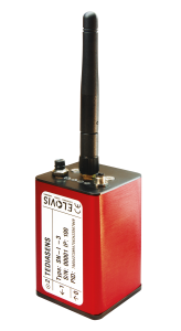
TEDIASENS-SN-I (Sensor-Node-internal)Sensor Node Type SN-I (Sensor-Node-Internal) are equipped with a 3-axis accelerometer.
|
 |
TEDIASENS-SN-X (Sensor-Node-external)Sensor Node Type SN-X (Sensor-Node) offers 3 BNC sockets in order to connect external sensors. The SN-X are identical with SN-I sensor nodes, except:
|
 |
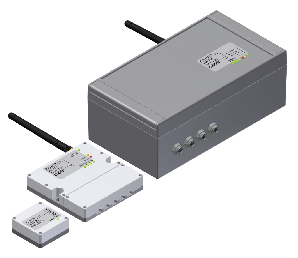
TEDIASENS-LN Series (Logging-Node)In addition to the TEDIASENS systems, which are used for synchronous live measurement data acquisition and are often used for short measurement times with online evaluation, ELOVIS develops customized LOGGING-NODE systems for long-term condition monitoring of machines or systems with radio connection. Depending on the type, LOGGING-NODE measurement systems are created with internal and external sensors for different measuring quantities. The measured data can be continuously or periodically monitored and recorded over several years. Selected measurement data, alarms or preprocessed signal characteristics are transmitted by radio to a gateway, which provides the data to the network. Compared to wired condition monitoring systems, the LOGGING-NODE systems offer the following advantages:
|
 |
Technical Data – Wireless Data Transmission Vibration and Oscillation Measurement Systems – Synchronous Measurement Data Transmission
| TEDIASENS | SN-I | SN-X | LN-I / LN-X / LN-XT |
| Type of Radio Node | Sensor node with internal sensor technology | Sensor node for connection of external sensor technology | Sensor node with internal sensor or for connection of external sensor technology |
| Radio Interface | WLAN | WLAN | 2,4 GHz IEEE 802.15.4 |
| Monitoring Type | Continuously | Continuously | Periodically or continuously |
| External Measurement Channels | None | 3 sensor channels per node | Depending on application |
| Integrated measurement channels | 3 Acceleration sensors per node | None | Up to 4 |
| Integrated sensor technology | Acceleration | – | Acceleration piezoelectric, position, temperature, geophone, MEMS, slope |
| Measurement Range | ±10 g (optional: ±100 g) | Input voltage range ±1 V; ±10 V available | Depending on application |
| Measurement Accuracy | 2 mg (RMS) [at ±100g -> 5 mg] | – | Depending on application |
| Sensor connection / interfaces external channels | – | optionally BNC or LEMO; IEPE supply 18 V; 2mA; switchable | 0…5 V, ± 5 V, 0…10 V, 4 – 20 mA, R-Measurement Bridge, digital |
| Input Coupling | – | AC/DC available | Depending on application |
| Bandwidth | 1 Hz – 8 kHz (-3dB) | DC/0,4 Hz – 8,6 kHz (-3dB) | Depending on application |
| AD converter resolution | 24bit | 24bit | 16 bit or 24 bit |
| Sampling rate / data acquisition | max. 13 kHz per channel | max. 13 kHz per channel | ≤40 kHz at 16-Bit |
| SNR | 109,5dB (RMS, broadband) | 109,5dB RMS broadband | Depending on application |
| Channel Sampling | Simultaneously | Simultaneously | Depending on application |
| Synchronicity | 1 µs standard deviation | 1 µs standard deviation | Optional |
| Data rate per sensor node | 1 MBit/s | 1 MBit/s | Depending on appcliation |
| Sensor nodes per system | 1 to 40 (typically: 10) | 1 to 40 (typically: 10) | depending on application |
| Range free field 802.11g | 138 m isotropic | 138 m isotropic | depending on application |
| Power Supply | interneral battery / power supply unit optionally (lower analog performance) | interneral battery / power supply unit optionally (lower analog performance) | internal battery or 10-30 V power supply |
| Measurement Period | typ. 7-9 h in battery mode | typ. 7-9 h in battery mode | 1 – 10 Years |
| Battery Charge Time | Max. 3 h | Max. 3 h | Depending on application |
| Operation | 1 switch, or via driver software | 1 switch, or via driver software | Depending on application |
| Display | 4 LEDs (wireless or battery mode) | 4 LEDs (wireless or battery mode) | Depending on application |
| Dimensions | 40 x 40 x 82 mm³ (without antenna) | 114,1 x 63,5 x 30,0 mm³ (without antenna) | ab 50 x 50 x 20 mm³ |
| Weigth | 220 g | 270 g (including battery and antenna) | ab 30 g |
| Protection Class | IP 67 | IP 54 | IP 54, on demand up to IP 67 |
| Storage | – | – | up to 4 Mio. measurement values (when using microSD card up to 4 billion measurement values) |
| Measurement Trigger | – | – | Schedule, Vibration, exceeding thresholds, radio |
Accessories – Wireless Data Transmission Vibration and Oscillation Measurement Systems – Synchronous Measurement Data Transmission
Standard Accessory |
|
Plug-In Power Supply TDS-PS |
The Plug-In Power Supply TDS-PS serves as a charging unit and can be used for all TEDIASENS radio nodes. |  |
|
Access Point TDS-AP |
The standard access point for the TEDIASENS radio nodes has its power supply via USB. The data communication works via Ethernet network. |  |
|
Accelerometer TDS-ACC
|
Single-axis accelerometer with BNC connector for SN-X sensor nodes | 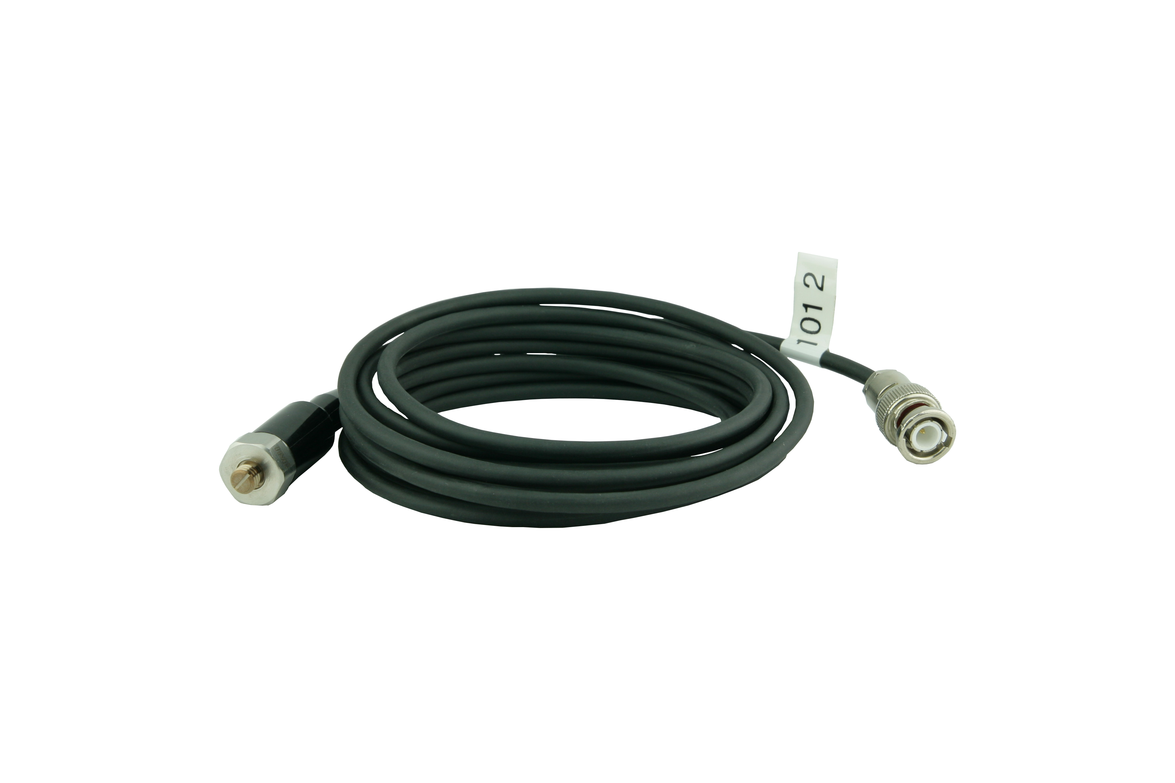 |
| Additional Battery
TDS-EAP |
The additional battery extends the operating time of the radio nodes by up to 9 hours. | |
| Rugged
TDS-SNX-R
|
The Rugged impact protection protects the SN-X sensor nodes against damage. | 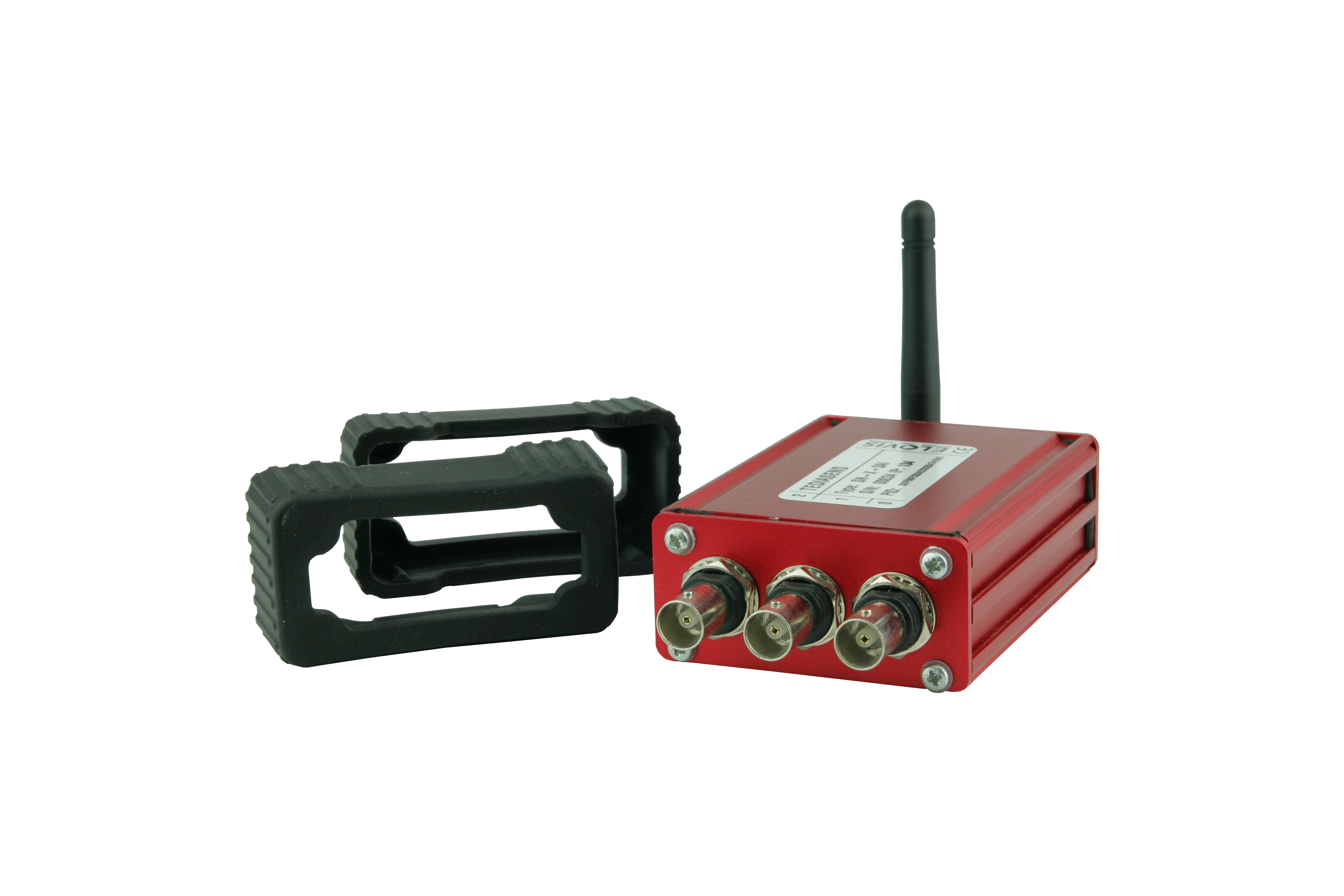 |
Mobile Equipment |
| Magnetic Base
TDS-MF |
Magnetic base for easy and fast mounting of SN-I radio nodes on or in machines with metallic measurement positions. | 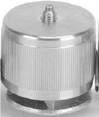 |
| System Case
TDS-CASE |
The ELOVIS Transport Cases CASE, which is available in different sizes, are ideal for safe storage and transport of sensor components. |
Software |
| PC Software
TDS-GUI |
The TDS-GUI configuration and monitoring software is used to operate, display and store TDS measurement values on a PC, laptop or tablet computer. | 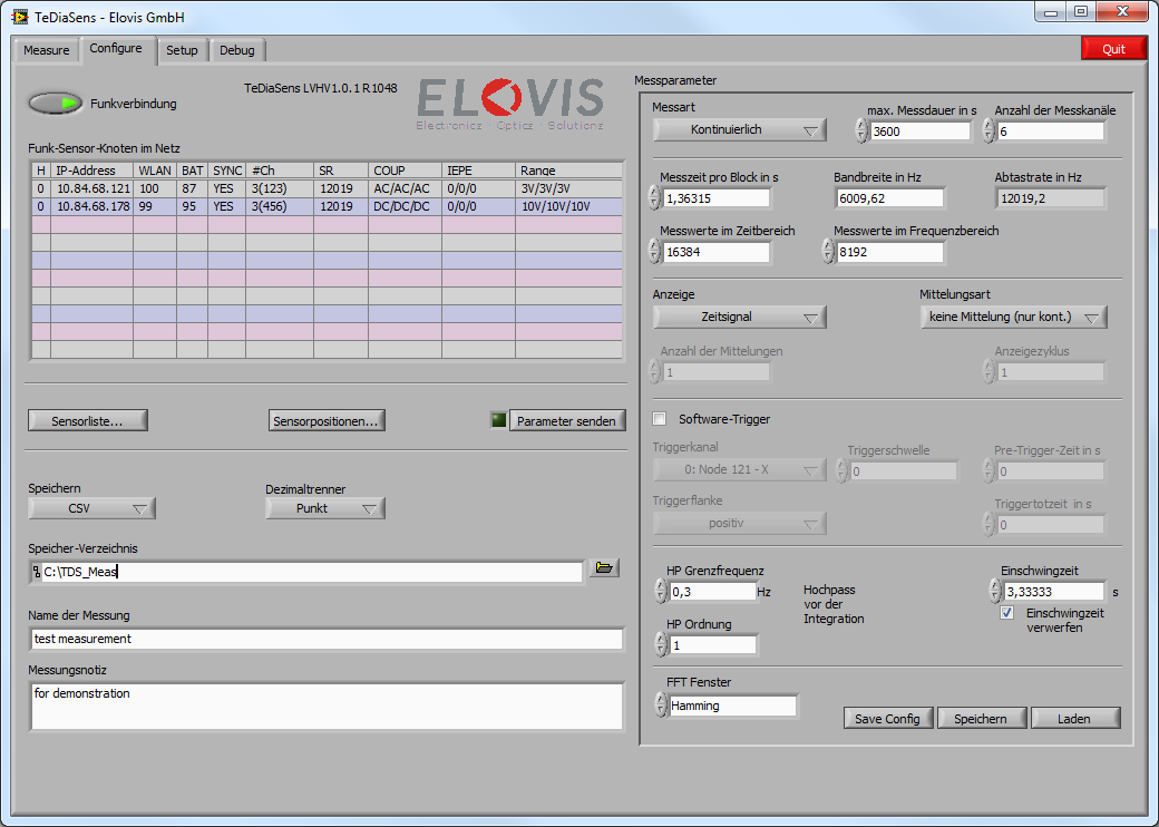 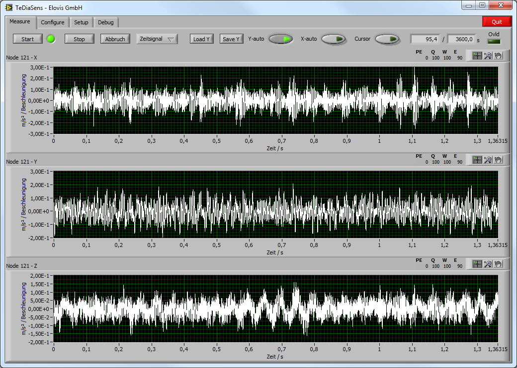 |
Wireless Data Transmission Vibration and Oscillation Measurement Systems – Synchronous Measurement Data Transmission
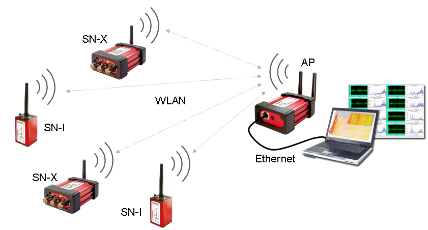
SN-X: Sensor Node External
– Radio node for connection of external sensors (3 IEPE channels)
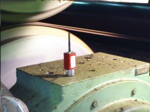
SN-I: Sensor Node Internal
– Radio node with integrated 3-axis accelerometer
AP: Access Point
– Wireless LAN: 802.11g
PC communication
– ELOVIS GUI: graphical user interface – LabView based
Videos – Wireless Data Transmission Vibration and Osciallation Measurement Systems
| Product Video – TediaSens
Video regarding Wireless Data Transmission Vibration and Oscillation Measurement Systems Synchronous Wireless Measurement Data Transmission Product Tutorial and Application Overview |
 |
Downloads – Wireless Data Transmission Vibration and Osciallation Measurement Systems – Synchronous Measurement Data Transmission
|
|
|
|
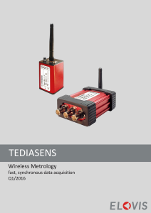
TEDIASENS – Product Overview |
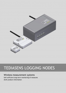
LOGGING NODES – Product Data Sheet |
Wireless synchronous measurement data transfer
Should measurement data be transmitted wirelessly and synchronously? You do not find a sufficiently powerful, self-su...
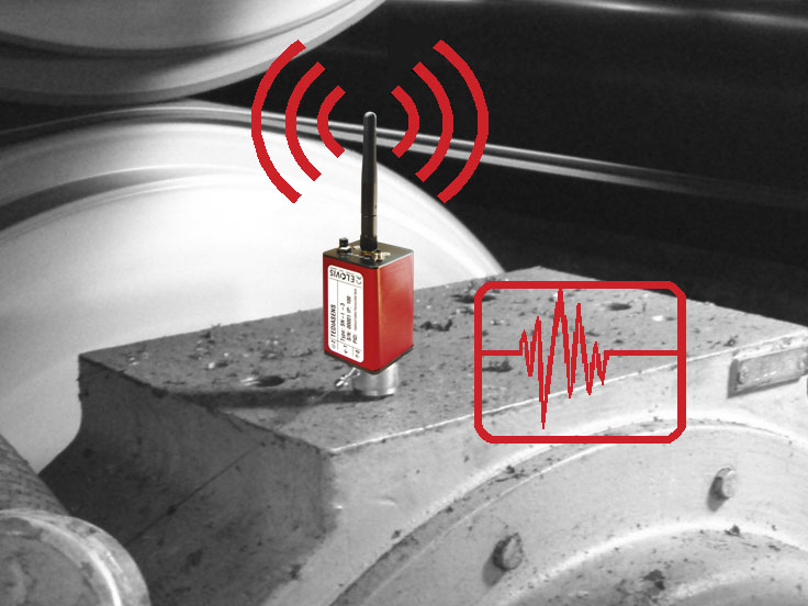
Vibration & Oscillation Measurement
In trouble shooting, vibration measurements must be carried out quickly and easily at different measurement points. C...
Long-Term Monitoring
Measurement Data Logging
Object states should be monitored over a longer period of time at regular intervals, whereby the test data and any al...
Wireless Machine Monitoring
The machine service requires reliable measurement equipment, which can be used quickly and safely. With the ELOVIS wi...
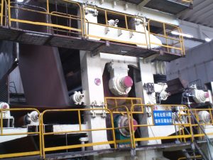
Vibration Measurement in the Paper Machine
Due to their size and complexity, paper machines are a challenge in vibration trouble shooting. With the ELOVIS wirel...
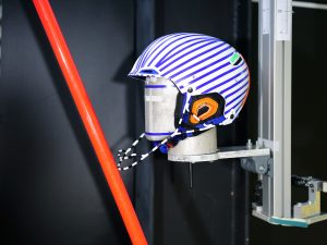
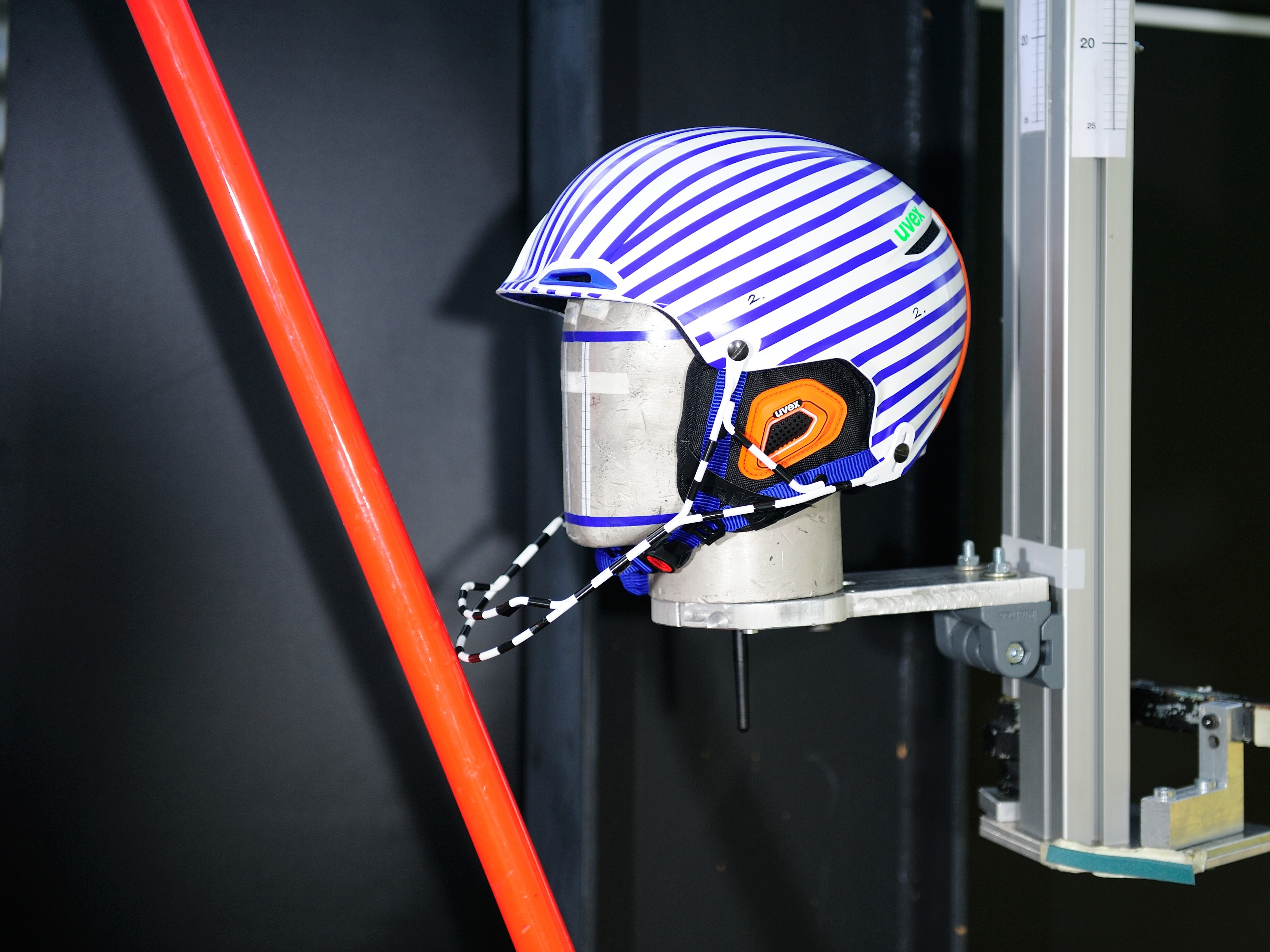
Impact Test and Acceleration Measurement
Helmets for sport and road traffic have to meet high safety requirements. The decisive point is the effect of impacts...